HP Clock

Sunday, May 20, 2012

Eclipse Viewing with Junk Box Parts

Backyard astronomy is always fun, and it doesn't get much better than a solar eclipse.  I set up my small spotting scope today for neighborhood kids to safely view the eclipse.  One of the safest ways that I know of is to use the telescope to project an image of the eclipse on to a screen.  Here is the screen I built from aluminum from the hardware store and a small piece of foam core available from any office supply store.

I also used a simple clock drive I built using a wide assortment of junk box parts.  The design was mostly based on adapting the other parts to the found worm drive.

With a way to project the image on to a screen and a clock drive that would compensate for the earths motion I was ready to watch the eclipse.  Here you can see all the parts coming together.  The added lead dive weight is used to take out slop in the gears of the drive train.  This picture was taken just as the eclipse was starting.

This picture was taken right at the height of the solar eclipse event.  The air was noticeably cooler and ambient light was less.

Sunday, May 6, 2012

Additional Pentode Information


I finally got around to posting additional details of the miniature pentode test fixture, including a schematic and list of tubes.  Although I built the test fixture primarily to work with 6AU6 tubes the pinout of that tube is so common that just like the dual triode test fixture there is a long list of other tube types that can be tested.  There are basically three basing diagrams that can be used with this fixture.  Here are the three bas diagrams and the list of tubes that should be supported.


Tube Heater Voltage Diagram
EF95 6.3 VAC 7BD
EF93 6.3 VAC 7BK
6JH6 6.3 VAC 7CM
6JH6 6.3 VAC 7CM
6HZ6 6.3 VAC 7EN
6HS6 6.3 VAC 7BK
6GY6 6.3 VAC 7EN
6GX6 6.3 VAC 7EN
6GM6 6.3 VAC 7CM
6EW6 6.3 VAC 7CM
6DT6A 6.3 VAC 7EN
6DK6 6.3 VAC 7CM
6DE6 6.3 VAC 7CM
6DC6 6.3 VAC 7CM
6CF6 6.3 VAC 7CM
6CE5 6.3 VAC 7BD
6CB6A 6.3 VAC 7CM
6BZ6 6.3 VAC 7CM
6BJ6 6.3 VAC 7CM
6BH6 6.3 VAC 7CM
6BC5 6.3 VAC 7BD
6BA6 6.3 VAC 7BK
6AU6 6.3 VAC 7BK
6AK6 6.3 VAC 7BK
6AK5 6.3 VAC 7BD
6AH6 6.3 VAC 7BD
6AG5 6.3 VAC 7BD
12EK6 12.6 VAC 7CM
12DZ6 12.6 VAC 7CM
12CX6 12.6 VAC 7CM
12BZ6 12.6 VAC 7CM
12BL6 12.6 VAC 7CM
12BD6 12.6 VAC 7CM
12BA6 12.6 VAC 7CM
12AW6 12.6 VAC 7CM
12AU6 12.6 VAC 7BK
12AF6 12.6 VAC 7CM

    Here is the schematic of the Pentode test fixture


Friday, March 23, 2012

More DIY IR Jammer

I did breadboard and test the DIY IR jammer last weekend but it’s taken me this long to carve out a minute to post the results.  The schematic is correct and only took a few minutes to re-create on the plugboard.  For power I used a small bench supply set to 6 volts to duplicate four AA cells.  When I powered up the circuit it oscillated just as predicted, but the frequency of oscillation did not agree with LT Spice.  The first time I entered in the schematic I just picked an arbitrary Op Amp from those provided by Linear Technology.  That is what caused the discrepancy.  I tracked down a TL082 model and that provided results that are nearly identical to the actual circuit.  Here is a screen shot of the LT Spice schematic including the spice directives used to add the external model.

So the lesson here is use the correct model for accurate results.  I’m including the TL082 model I used in the body of the post.  Just copy and paste it into a text file adding a .sub extension if you want to do your own simulation.

TL082 Spice Model

*****************************************************
* TL082 OPERATIONAL AMPLIFIER "MACROMODEL" SUBCIRCUIT
* CREATED USING PARTS RELEASE 4.01 ON 06/16/89 AT 13:08
* (REV N/A)      SUPPLY VOLTAGE: +/-15V
* CONNECTIONS:   NON-INVERTING INPUT
*                | INVERTING INPUT
*                | | POSITIVE POWER SUPPLY
*                | | | NEGATIVE POWER SUPPLY
*                | | | | OUTPUT
*                | | | | |
.SUBCKT TL082    1 2 3 4 5
*
  C1   11 12 3.498E-12
  C2    6  7 15.00E-12
  DC    5 53 DX
  DE   54  5 DX
  DLP  90 91 DX
  DLN  92 90 DX
  DP    4  3 DX
  EGND 99  0 POLY(2) (3,0) (4,0) 0 .5 .5
  FB    7 99 POLY(5) VB VC VE VLP VLN 0 4.715E6 -5E6 5E6 5E6 -5E6
  GA    6  0 11 12 282.8E-6
  GCM   0  6 10 99 8.942E-9
  ISS   3 10 DC 195.0E-6
  HLIM 90  0 VLIM 1K
  J1   11  2 10 JX
  J2   12  1 10 JX
  R2    6  9 100.0E3
  RD1   4 11 3.536E3
  RD2   4 12 3.536E3
  RO1   8  5 150
  RO2   7 99 150
  RP    3  4 2.143E3
  RSS  10 99 1.026E6
  VB    9  0 DC 0
  VC    3 53 DC 2.200
  VE   54  4 DC 2.200
  VLIM  7  8 DC 0
  VLP  91  0 DC 25
  VLN   0 92 DC 25
.MODEL DX D(IS=800.0E-18)
.MODEL JX PJF(IS=15.00E-12 BETA=270.1E-6 VTO=-1)
.ENDS


Here is the revised spice plot followed by the actual waveforms that I recorded with my oscilloscope. 

It’s easy to see how well the simulation agrees with the hardware.

I came up with two simple tests to confirm that the circuit was actually emitting infrared pulses.  The first test was to simply point a video camera at the LEDs while the circuit was on.  This picture shows this basic setup.

Even the cheapest of video cameras will show infrared light.  The infrared light shows as a pale blue in this picture I took of the video monitor.

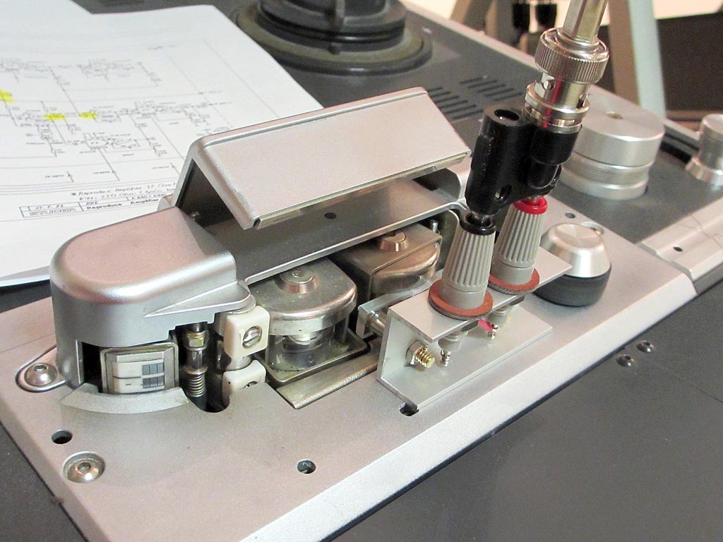
The next test was equally as easy and simply involved attaching a photodiode to an oscilloscope, and then pointing that photodiode at the IR LEDs.  The resultant pulses can be easily seen here.

Did it work??

I took the lab supply with the plugboard on top into the living room and set it on the coffee table and flipped the power supply switch on.  Admittedly my setup is not very covert, but it did successfully disable the remote's ability to change channels.

Thursday, March 15, 2012

DIY IR Jammer Missing Information

The GREAT CREATE at Radio Shack is truly a well-intentioned and worthwhile exercise for getting kids interested in electronics and technology.  It harkens back to the Radio Shack I new as a child where I could find all the bits and pieces for my projects.  I found a brochure in the local Radio Shack that supposedly provided instructions on building a infrared remote jammer. 

I say supposedly because on closer inspection the brochure was filled with errors and missing information such that any kid trying to build it would have been met with disappointment and frustration.  Projects like this done properly can be an inspiration that jumpstarts a career in science or engineering. Improperly presented they can turn a young mind away from a potentially great learning experience.  With that in mind I posted the missing schematic and an explanation of how the circuit works, along with a spice simulation.

The Schematic;
The schematic breaks down into two major blocks with the first being a relaxation oscillator built around the TLO82 FET opamp, and the second being a current driver that uses the BJT transistor to convert the output of the oscillator into current drive for the infrared light emitting diodes.

The relaxation oscillator works by using the opamp as a comparator.  The charging and discharging of the RC network comprised of R11, R10, and C3 which is fed into the inverting input of the opamp causing the output to change states positive to negative every time the node of R10 and C3 reaches the 3 volt compare point set on the non inverting input.  That 3 volt point is is set by the voltage divider R12 and R5.

The diode driver works by AC coupling the signal out of the opamp through C1 directly into the base of the transistor.  The resulting pulses drive the transistor from cutoff to near saturation.  10 ohm resistor R7 provides current limiting through the diodes.  


Spice Simulation; 
All of this can be demonstrated by viewing the graph I created using LT Spice.  LT Spice is one of the best free programs available for simulating electronic circuits and can be found on Linear Technologies Web site.  I highly recommend it.  As for the simulation it shows the first 200 microseconds of the circuit, at which point it reaches steady state oscillation.  This graph shows the RC circuit in red, the opamp output in blue, and the diode current in green.  I may take time this weekend to build up the circuit to see if it works and matches the simulation.  If I do there will be pictures.

Critique of the Brochure;
  1. The two pictures of the circuit are rotated 90 degrees making it difficult to trace out.
  2. The shopping list is wrong and calls out only two 10k resistors, while the circuit requires 6 10 K resistors.
  3. No schematic or no link to a schematic.
  4. No explanation on how it works.

Tuesday, February 21, 2012

Testing Miniature Pentodes with the Tek 575

This post is a follow on to my January 6th post “Testing Dual Triodes with the Tek 575”.  With the great success of my dual triode test fixture making it possible to go through boxes of tubes I decided to take on making a fixture for the 6AU6 which is the next most common tube I encounter in much of the antique test equipment that I restore or repair.  The 6AU6 is a miniature pentode and as such would require a screen grid supply of about 100 volts to test properly.  I was torn between making a small switcher and just using back-to-back filament transformers.  This was incentive enough for me to create a breadboard to test out the concept and to see what the volume would be of the components being used.  Here is a picture of the breadboard under test.  The bench supply is for the added digital meter used to monitor the screen grid supply.

Once I was satisfied with the design and the performance I shoehorned it all into the same SERPAC A-42 enclosure that I had used to package the dual triode tester.  As you can see there was a lot more to fit inside, including the screen grid supply, 5 volt supply for the meter, and the meter.  I also found it necessary to add ferrite beads to the wires coming from the Tek 575.

Here is the completed unit ready to go.  As with the previous test fixture power is supplied through a standard IEC power cord.  It’s also worth noting that I added a second 7-pin socket that allows me to switch between two tubes for the purpose of matching.

This is a picture of the pentode test fixture in use. 

Here you can see that the results are quite nice and comparable to the data in the RCA tube manual.  This picture was taken with a modified C-12 camera mount described in an earlier post on this blog.

I was also pleased to discover that just like the dual triodes there is a large list of miniature pentodes that have the same or similar pinouts that can all be used with this fixture.  I’ll add the list at the end of the documentation for this project just as I did for the dual triode fixture.  It will most likely be posted on the Tek Scopes forum;


As usual if you decide to try this on your own I offer the following disclaimer:

Some of the circuits described on this site use or generate potentially lethal electric currents and voltages, and if not treated with care, respect and intelligence, they can result in fatal injury. If you use the information on this site to kill yourself, your friends, family members, acquaintances, total strangers, pets, electronic devices or burn down your house, it is not my problem.  That said, have fun!

Wednesday, February 15, 2012

How Many Bits Can You Use?


I have often wondered at what point the digital conversion process for audio reaches a point of demensishing returns, or at least unrealized expectations in the performance of the converters.  We live in a noisey world, and even before digital audio noise in electronics has always been with us and has always been the enemy of dynamic range.  Noises generated internally in electronic circuits are produced mostly by molecular activity. The random motion of electrons is directly related to the temperature of the conductors, and components that make up a circuit. That thermal noise generated is well understood and can be expressed in the equation as:
(eq. 1)

K = Boltzman’s constant 1.38 x 10 –23 joules per degree Kelvin
T = absolute temperature in degrees Kelvin
R = equivalent load resistance across which Et is measured
Δf = bandwidth in Hertz

Substituting 293 degrees (room temperature in degrees Kelvin), 20 Khz bandwidth, and an r of 600Ω s Et can be calculated as .22 μvolts. Voltage can be solved for where Dbm is defined as one mili-watt across 600Ω. 


(eq. 2)

Solving this equation for a conversion from volts to DBm gives the equation:
(eq. 3)
Inserting the .22 micro volts gives a noise floor of -130.9 db.  From here the number of bits required to digitize information can be calculated.
(eq. 4)
This works out to 21.8 bits. The digital resolution based on the number of bits can be solved for with the formula:

(eq. 5)

If we could create a converter that defied the laws of physics, and in particular the laws of thermo dynamics, one could expect a 24-bit converter to have a dynamic range of 144 db. Remember, that at 96 kHz sampling the delta f is doubled increasing the noise floor to .311 μvolts or a dynamic range of 127.9 db, which would require 21.3 bits. For a 192 kHz sample rate the bandwidth is about 80 kHz, raising the noise floor to .44 μvolts. Dynamic range is 124.9 db, with 20.8 bits as the theoretical limit.

It’s also important to note that these are calculations based on an ideal noise free environment and do not include any provision for shot noise. Like thermal noise, shot noise is a function of the electron charge, the magnitude of the current, and the bandwidth of the circuit under test. This noise occurs at boundaries where the conducted electron must cross from one type of material to another. This would include things like Vacuum tubes and solid-state junctions. Shot noise is usually expressed as a current. Even here it can be seen that the addition of bandwidth will increase the noise and reduce the dynamic range.

(eq. 6)
e = The charge of one electron (1.6 x 10 to –19th)
I = The current through the junction in amperes
Δf = bandwidth in Hertz


Realistic Analog Playback

The average analog deck outputs +4 dbm at zero VU. This translates into a voltage of 1.23 volts. Lets assume that there will be peak excursions 16 db above the zero vu setting for a total of 20 db above zero dbm. This would mean a maximum voltage of about 7.75 volts. Now lets imagine an analog tape deck working perfectly with Dolby SR noise reduction such that the signal out has a dynamic range of 85 db. Subtract the 20 db from this figure to arrive at a noise floor of -65 dbm. This would mean the smallest signal one would expect to see would be on the order of 436 μvolts If we accept the 24-bit converter can digitize to a theoretical maximum accuracy of between 20 and 22 bits, then the resolution will be between 7.39 μvolts and 1.85 μvolts.

(eq. 7)
Using the mean of 21 bits for individual transitions of 3.7 μvolts the lowest expected signal could be digitized to within 117.8 discreet values. 

(eq. 8)
The number of bits can be calculated from the number of symbols assuming all symbols are equi-probable from the standard information theory equation for entropy in bits per symbol. 

(eq. 9)

This would give a value of 6.88 bits per symbol at the lowest analog signal level. As a point of comparison the same 436 μvolts signal would be represented by only 3.68 symbols or 1.88 bits with 16 bit digitization.  So where does this leave us?  As you can see anything past 21 bits is past the physical limits of what is achievable by any digital conversion process.  Although some may feel that human perception extends beyond 40 KHz they cannot dispute that added bandwidth can reduce the ability of a digital converter to operate at it's maximum bit depth.  The loss of one bit in bit depth translates into one half of the resolution of that digitizing process.


Friday, February 3, 2012

Building and Using a Flux Loop


It’s always fun to revisit old analog techniques that if not forgotten they are at least not used as much as they should be.  One such trick for me is the use of a flux loop in conjunction with troubleshooting reproduce electronics in analog tape decks.  In this case an anomaly in the phase display of a low frequency tone was noticed.  Two things were wrong.  First, there was a phase discrepancy between the left and right channel of the deck indicated by an opening of the phase display.  Second, the phase display was not an oval, but instead was more of a tear drop shape.  As the playback frequency was increased both problems disappeared.  

Looking at the phase shift and distorted phase plot would most likely suggest a problem in low frequency coupling in the reproduce electronics.  To confirm this I built the simple flux loop seen in this picture out of parts in the junk box.

Essentially a flux loop is a means of generating magnetic flux and applying it to a tape deck head in such a way as to induce a field in the head which closely approximates the field from a moving length of tape. A typical flux loop is simply a few turns of fine wire wound closely together on a non-ferrous rectangular former.  In my case a small piece of Plexiglas filed into the correct shape worked fine.  A 620-ohm resistor in series with this coil was added in an attempt to match the impedance of the HP 200 CD audio oscillator.  Here you can see the flux loop placed in proximity of the playback head of the deck.

With the flux loop in place all one needs to do is simply turn on the deck, place it in playback, and hook up an oscilloscope to the output.  The complete setup, including the oscillator, flux loop, tape deck, and oscilloscope can be seen here.

Here is a block diagram of the test setup.


With this test setup, and a few card swaps the bad reproduce card was quickly identified.  All of this was done without playing back a test tape.  In this picture the distortion is obvious, and likely caused by a bad electrolytic coupling capacitor. 

The next step will be to put the faulty card on an extender, and use the oscilloscope to identify the bad component.

Friday, January 6, 2012

Testing Dual Triodes with the Tek 575


I’ve been following a thread on the Tek Scopes forum 


discussing curve tracers with some interest since I recently acquired a second Tektronix 575.  I picked it up because it looked to be in good shape and it has the option that takes the collector voltage up to 400 volts.  A brief clean up and repair restored it to operating condition.  Here it is as purchased:

As you can see it was really dirty and dusty inside, and looks like it had been sitting unused for a very long time;


I’m lucky enough to have restored a Tektronix 570 tube tester that I actually still use at the office to check, test, and match tubes for various pieces of gear used by the audio engineers and mixers. Recently we were testing a pre amp that used a large number of 6DJ8 dual triodes. 


Inspired by the TekScopes thread and the tedium of patching on the 570 I decided to make a test fixture for the newly refurbished 575.  I have to say it works great and is perfect for quickly testing a large variety of dual triodes since many of them have the same pin out.  Here is the inside of the dual triode test fixture being wired;


Here is a picture of the completed tester:


And finally here is the tester being used to go through a box of used dual triodes:

I had to laugh, because when I brought in the text fixture and proudly showed it off to one of my colleagues, he asked what a 575 looked like.  No problem.  I went to Google images and one of the top search results was the image on this site.  (scroll down al little.)


So….not an original concept, and they are even testing the same tube.  

There is a PDF in works that I will post for anyone that want to try this.  That said, I will offer the usual disclaimer. Some of the circuits described on this site use or generate potentially lethal electric currents and voltages, and if not treated with care, respect and intelligence, they can result in fatal injury. If you use the information on this site to kill yourself, your friends, family members, acquaintances, total strangers, pets, electronic devices or burn down your house, it is not my problem.