
It’s always fun to revisit old analog techniques that if not forgotten they are at least not used as much as they should be. One such trick for me is the use of a flux loop in conjunction with troubleshooting reproduce electronics in analog tape decks. In this case an anomaly in the phase display of a low frequency tone was noticed. Two things were wrong. First, there was a phase discrepancy between the left and right channel of the deck indicated by an opening of the phase display. Second, the phase display was not an oval, but instead was more of a tear drop shape. As the playback frequency was increased both problems disappeared.

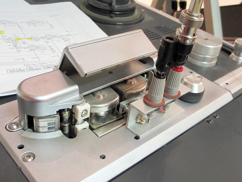
Looking at the phase shift and distorted phase plot would most likely suggest a problem in low frequency coupling in the reproduce electronics. To confirm this I built the simple flux loop seen in this picture out of parts in the junk box.

Essentially a flux loop is a means of generating magnetic flux and applying it to a tape deck head in such a way as to induce a field in the head which closely approximates the field from a moving length of tape. A typical flux loop is simply a few turns of fine wire wound closely together on a non-ferrous rectangular former. In my case a small piece of Plexiglas filed into the correct shape worked fine. A 620-ohm resistor in series with this coil was added in an attempt to match the impedance of the HP 200 CD audio oscillator. Here you can see the flux loop placed in proximity of the playback head of the deck.
With the flux loop in place all one needs to do is simply turn on the deck, place it in playback, and hook up an oscilloscope to the output. The complete setup, including the oscillator, flux loop, tape deck, and oscilloscope can be seen here.

Here is a block diagram of the test setup.

With this test setup, and a few card swaps the bad reproduce card was quickly identified. All of this was done without playing back a test tape. In this picture the distortion is obvious, and likely caused by a bad electrolytic coupling capacitor.

With this test setup, and a few card swaps the bad reproduce card was quickly identified. All of this was done without playing back a test tape. In this picture the distortion is obvious, and likely caused by a bad electrolytic coupling capacitor.

The next step will be to put the faulty card on an extender, and use the oscilloscope to identify the bad component.