HP Clock

Sunday, December 6, 2020


Pi Arduino Development Station

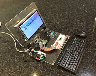
Having picked up a folding Plexiglas prototyping assembly for a few dollars at the amateur radio swap meet I decided to use it to build a portable Raspberry Pi Arduino prototyping station. I could use the Raspberry Pi 4 to do hardware development directly and with the Raspian Linux operating system I would be able to run the Arduino IDE. The completed system consists of a Raspberry Pi 4, Arduino Uno, ten-inch HDMI display, and a USB receptacle outlet for power.


Fig. 1 Combination Raspberry Pi Arduino Dev Station

Here you can see where I added a prototyping board that includes a GPIO breakout connector for the Raspberry Pi. As with most of my prototyping setups I like to add an aluminum angle bracket to hold some BNC connectors for easy IO and banana jacks with ¾” spacing for connecting external power. I can also add potentiometers as needed.

Fig. 2 Closeup of Prototyping Section

Here is a view of the banana jacks used for connecting external power supplies. You can also see how easy it is to either probe or inject signals with the BNC connectors.

Fig. 3 Banana Jack Power Connections

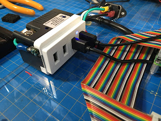
The USB receptacle outlet provides plenty of power for the Raspberry Pi, Arduino and HDMI display. The exposed connector on the top is neutral, however it has since been covered as well.

Fig. 4 Modified USB receptacle

Here is where the completed project comes together where the Arduino is driving and reading an arrangement of gates and counters in a simple ‘Hello World” test.

Fig. 5 Development Assembly Running

Here is a picture of the development assembly folded up and ready for travel.

Fig. 6 Folded up for Travel

Resource Links

Wednesday, November 25, 2020


A Simple ESR Meter

I was always envious of my friends analog ESR meter that allowed him to check and find bad capacitors while they were still in circuit. The particular meter he had is no longer available, which meant doing some research to understand how they worked and to come up with my own version. First, what is ESR? ESR stands for the equivalent series resistance of a capacitor. ESR is frequency-dependent, temperature-dependent, and changes as components age. It’s typically important for ‘Wet’ aluminum electrolytic capacitors used in power supplies to have a low ESR.

The typical method used for measuring ESR is to supply the capacitor with a known AC current (Icap) at some frequency where the capacitive reactance of the capacitor is very low so that the ESR dominates. By measuring the resulting AC voltage developed across the capacitor’s terminals (Vcap) the ESR can be determined with Ohm’s law:

ESR = Vcap/Icap

Most of the designs I found worked along the same lines as this block diagram:


Fig. 1 Typical ESR Meter Elements

Going from left to right there is an oscillator that supplies AC voltage to be applied to the capacitor. Next the AC signal is fed into an impedance converter and detector. The detected signal is then rectified and buffered so that it can drive the meter on the right of the diagram. Since the ESR meter is to be battery operated the power supply circuit supplies split rails for the operational amplifiers that will be used in the ESR meter. The oscillator in most of the examples I looked at operated at 100 kHz to 150 kHz. The driver used to reduce the impedance of the AC signal could be anything from a transistor current boost, transformer, or paralleled logic gates. The detector was usually back to back diodes. The detected AC signal is then rectified, amplified and fed into a DC meter.

In the circuit I decided to build I used several design elements from the DIY examples I found on the Internet.


Fig. 2 Schematic of the ESR Meter

For the oscillator and impedance converter I used a single 74HC14 that provides 6 inverters with hysteresis. One of the inverters acts as a relaxation oscillator and the remaining 5 inverters operate as the impedance converter. This part of the circuit came from Lawrence P. Glaister VE7IT. The detector portion of the ESR meter is the same as the detection circuit in the commercial ESR meter built by Creative Electronics. Sadly, these meters are no longer made. Diodes D1 and D2 clip the top and bottom of the 100 kHz AC to one silicon junction drop. This allows capacitors to be tested in circuit because any other silicon junctions will not be forward biased by the relatively low AC signal.  The low-level AC signal is DC decoupled with C3 and amplified by two operational amplifiers, with a voltage gain of 4.7 for the first amplifier and a gain of 10 for the second. This provides an overall gain of 47 to the input of the absolute value circuit.The Absolute value circuit was taken from the Burr - Brown Application Bulletin “Precision Absolute Value Circuits”.  The absolute value circuit had plenty of drive for the 100 microamp meter I used.

This ESR meter operates of a single 9 volt battery. The plus, minus and ground voltages needed for the operational amplifier are derived using this opamp voltage follower with current boost.


Fig. 3 Power Supply Circuit

To test out the circuit I built up a conventional bread board. BNC connectors allow for easy monitoring of the various waveforms. Initially for testing I simply looked at the signals with an oscilloscope intead of the 100 micro amp meter.

Fig. 4 ESR Bread Board

In this picture you can see the output the oscillator as well as the output of the ESR meter while testing a 50-microfarad electrolytic capacitor.

Fig. 5 Oscilloscope Test

In this waveform dump from the oscilloscope you can see the difference between a capacitor with a high ESR in blue and a capacitor with a low ESR in orange.

Fig. 6 Waveform Data Showing High & Low ESR

Even before I was able to package the meter into a case I used it to trouble shoot our air conditioner by locating a bad motor capacitor.

Fig. 7 Checking Motor Capacitor

The completed ESR meter is sufficiently portable so that it can be used remotely and away from the work bench. Simple Post-It® Note calibration was accomplished with a handful of 2-ohm resistors. The ESR meter works like an ohm meter. Before measuring a capacitor, the leads are shorted together and the knob is adjusted for a full-scale reading (Zero ESR). Rotating the knob fully counter clockwise turns the meter off with a switch.


Fig. 8 Completed ESR Meter

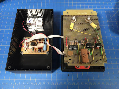
The circuit is wired on two prototyping Perfboards. The smaller board on the left is the circuit used to derive the plus, minus and ground references for the op-amps. The larger perfboard is the ESR meter circuit and it is held in place by the nuts on the meter.

Fig. 9 Inside the ESR Meter

Resource Links
Tuesday, April 28, 2020

Home Made UVC Sterilizer

This is a series of pictures describing a simple UV-C Sterilizer I built for mail, face masks, and small items. Much of it was built out of leftover parts from other projects. The germicidal lamps and ballasts were purchased on eBay. The timer and some electrical parts came from Amazon. Be warned! UV-C is very nasty, and at no time should you look directly at the bulbs or allow your skin to be exposed to the radiation. Any time that I energized the bulbs outside the enclosure or with the enclosure open I wore welder's goggles and did not look directly at the lamps.


Fig. 1 Bread board of the lamp and ballast

This is the schematic of the UV sterilizer. Each lamp requires a separate magnetic ballast. A timer allows a user to select the amount of sterilization in minutes. Typically, 5 to 10 minutes should be sufficient for most objects.

Fig. 2 Schematic

The box I built to house the sterilizer was fabricated from spare Ikea shelves and other press board material I had in the shop. I glued aluminum foil to the interior wall of each piece of box. I then followed up with aluminum tape around the edges. The aluminum tape is the kind used for air conditioning duct repairs and can be found at Home Depot or Loews.

Fig. 3 Press board covered with foil and aluminum tape

After the individual pieces are covered with foil they can be assembled into a box. I used dry wall screws to attach the sides together. After the box is assembled I followed up with aluminum trim on the outside edges for extra strength.

Fig. 4 Assembly of the press board box

Next I wired the junction box for the hot and neutral buss that feeds each of the lamps. I used a typical barrier strip and plastic project box. Rubber grommets were added to the box to protect the wires entering the box. The ballasts and G23 sockets use solid wire which works well with the screw terminals on the barrier strip.

Fig. 5 Close up of junction box

With the box completed I attached the junction box to the back of the unit.

Fig. 6 Junction box attached to the sterilizer

After the junction box was installed I attached the individual ballasts to the back of the sterilizer.

Fig. 7 Philips LPL-5-9 ballasts

Next I screwed down and wired the sockets for the germicidal bulbs. These particular bulbs required a G23 base. These can be found on Amazon for a few dollars. After the bulb bases were installed I drilled small holes for the wire from the ballasts and the neutral buss.

Fig. 8 Basses for G23 bulbs

I used a couple of wire in-baskets to suspend anything being sterilized over the top of the bulbs. This helps to optimize UV-C coverage and reduces fire risk by keeping objects being sterilized away from the bulbs.

Fig. 9 Wire baskets installed

Wiring at the back can now be completed. This includes running power from the junction box to the 2S electrical that I attached on the side. It is also time to put the cover on the black junction box. The 2S box houses the timer that will turn the germicidal lamps off after a sterilization time is selected. The timer I installed is a simple spring wound timer that can be set from 1 to 15 minutes. I have ordered a digital timer that has pre-set buttons for 5, 10, and 15 minutes. Both of these were found on Amazon.

Fig. 10 Caption for picture 10

The G23 sockets are installed and wired to the top of the box. After they are wired the top can be attached to the top of the enclosure.

Fig. 11 G23 sockets installed to top

With everything wired it was time to test the bulbs. Again, I wore welding goggles during the very short test.

Fig. 12 Lamps energized

I created a custom warning label based on OSHA samples found with Google Images. The size is based on a spare piece of Plexiglas I had in the junk box. I will provide a link to an SVG file that should work with almost any drawing program.

Fig. 13 Custom OSHA warning label

The last step is to attach the warning label to the front door of the enclosure and then attach the hinges to the door and the door to the enclosure.